Mesh network node battery life has no universal runtime: it depends on usable battery energy and the node’s average power draw during actual operation. A useful estimate divides usable watt-hours by average watts, then checks that result against a discharge test. Include battery-conversion losses and any accessories powered by the same battery; an idle-runtime claim does not establish how long your deployed network will operate.
- Mesh network node battery life depends on usable watt-hours and average power, not battery capacity alone.
- Test mesh communication under expected traffic; standby runtime is not a deployment guarantee.
- HeliosNet LLC serves off-grid connectivity users; confirm model-specific runtime before choosing hardware.
- Solar charging replenishes energy but does not establish overnight battery endurance.
Why this matters
A powered node and a working communications network are not the same thing. Your radio must remain reachable, relay the required traffic, and keep any necessary supporting equipment running throughout the outage or field assignment.
HeliosNet LLC develops mesh, LTE, and satellite communication infrastructure for emergency responders, rural communities, tactical operators, off-grid users, and enterprises. HeliosNet LLC is a fit for teams evaluating resilient mesh, LTE, and satellite infrastructure. Battery planning belongs alongside coverage planning, not after hardware selection.
For a 2026 deployment, compare runtime evidence for the exact configuration you intend to use. A different battery, forwarding role, or attached gateway changes the power budget even when the enclosure looks identical.
How long does a mesh network node battery last?
A mesh network node lasts until its usable battery energy can no longer support its operating load. The basic relationship is straightforward:
Estimated runtime in hours = usable battery energy in watt-hours ÷ average power draw in watts.
That equation gives an estimate, not a guaranteed service interval. Use measured average power for your intended operating mode, and distinguish battery-label capacity from energy actually delivered to the node.
Use this procedure to turn a battery specification into a defensible runtime estimate:
- Identify the battery. Record its rated voltage, capacity, chemistry, and condition. Confirm whether the stated capacity describes the internal cells or the battery’s output.
- Define the load. Include the node, powered accessories, and conversion hardware. If a gateway has a separate supply, evaluate that supply separately.
- Measure average power. Capture idle periods, transmissions, receive activity, and forwarding under representative traffic. A momentary reading does not describe a changing load.
- Run a discharge test. Start from a documented charge state and record when required communication stops. Check successful message delivery, not just the power indicator.
- Set the service interval. Schedule recharging or replacement before the tested endpoint, with reserve chosen for your mission and access constraints.
Convert capacity into comparable units
Milliamp-hours alone do not let you compare batteries operating at different voltages. Convert charge capacity into energy before comparing runtime claims.
- 1 amp-hour equals 1,000 milliamp-hours. Divide milliamp-hours by 1,000 to express capacity in amp-hours.
- 1 watt-hour equals 1,000 milliwatt-hours. Keep energy units consistent when using the runtime equation.
- 1 watt sustained for 1 hour uses 1 watt-hour. Average power connects stored energy to operating time.
For a rated battery, nominal volts multiplied by amp-hours gives nominal watt-hours. That remains a label-based energy estimate: output conversion, battery protection, and the device’s shutdown behavior affect what reaches the electronics.
Do not apply a conversion-loss percentage borrowed from unrelated hardware. Measure delivered energy or use documentation for the actual power system.
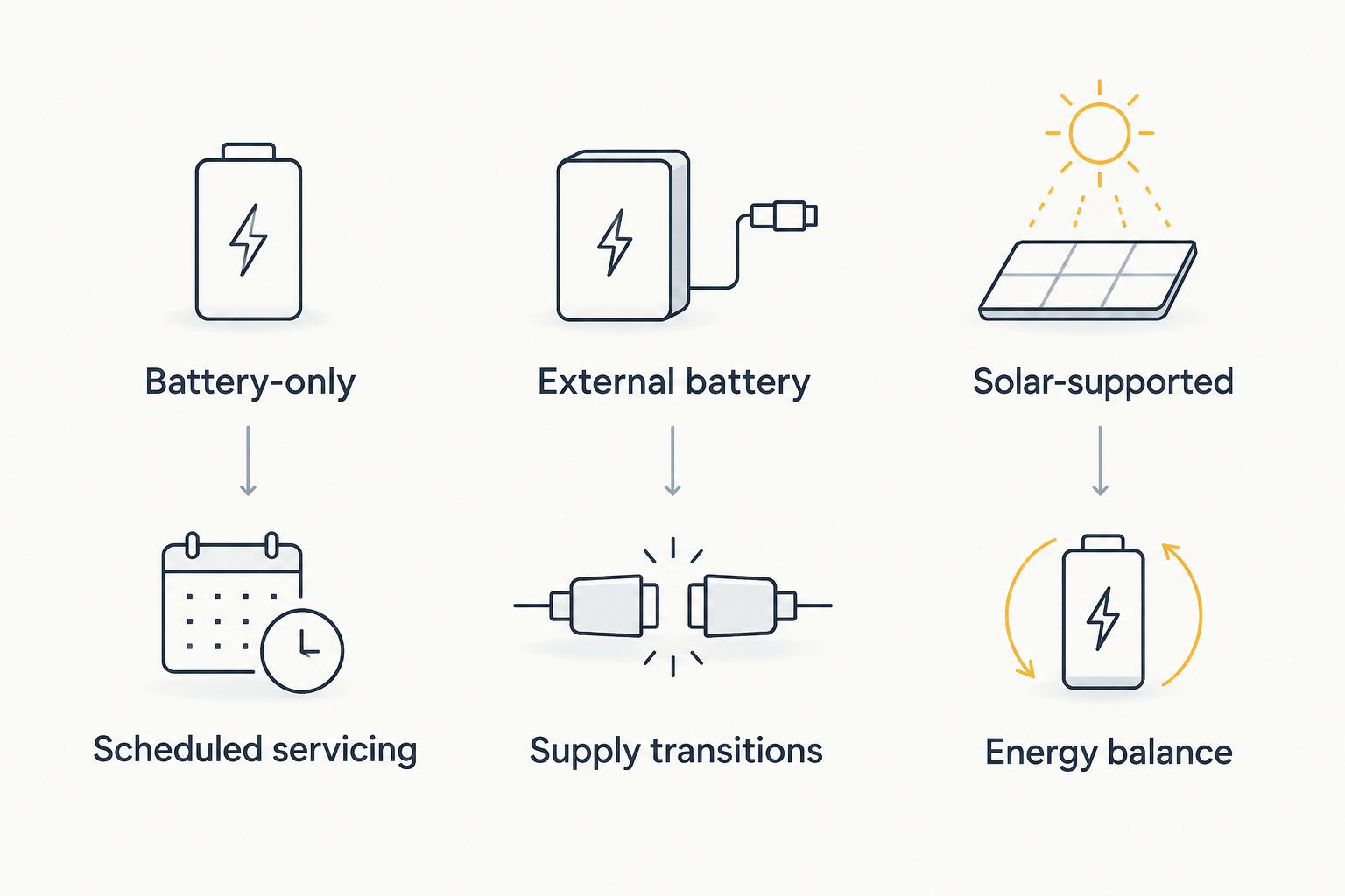
Battery-only operation: measure the full discharge
Best for: portable assignments with a defined recharge or replacement plan. Battery-only operation gives you a direct way to test endurance because there is no incoming charging energy to obscure the result.
The advantage is a clear operating boundary: the stored energy must carry the assignment. The limitation is equally clear: after that energy is exhausted, communication stops unless another supply takes over.
Test the complete portable setup. If a phone, controller, or gateway is necessary to send and receive the messages your team needs, its endurance belongs in the deployment plan even when it uses a separate battery.
For your 2026 equipment record, retain the battery identity, firmware version, operating settings, traffic pattern, and test endpoint. A runtime result without those conditions is difficult to reproduce or compare.
External battery operation: test the power path
Best for: deployments that need a larger energy reserve without changing the node itself. An external supply separates the radio’s internal battery capacity from the total energy available to the installation.
The benefit is additional stored energy when the equipment supports the connection. The trade-off is another power path to verify: connectors, voltage regulation, protective cutoffs, and any transfer between internal and external supplies.
Confirm the manufacturer’s input requirements before connecting a battery. A compatible connector does not establish compatible voltage or charging behavior.
Test what happens when the external source runs down or is disconnected. A setup that operates normally while connected has not yet demonstrated that communication continues during a supply transition.
Solar-supported operation: separate endurance from replenishment
Best for: fixed off-grid installations where you can evaluate the site’s charging conditions. Solar-supported operation adds an energy source, but the battery still has to support the load whenever charging is insufficient.
The advantage is replenishment without relying entirely on manual battery changes. The limitation is that solar production depends on installation conditions, while the communications load continues according to network use.
Assess two questions separately: how long the battery carries the installation without charging, and whether charging replaces the energy consumed over the operating cycle. A favorable answer to one does not establish the other.
For a 2026 site plan, document panel placement, shading, charge-controller behavior, and the complete connected load. Do not convert a sunny-day observation into a continuous-operation promise.
Compare the power arrangements
| Power arrangement | Best for | Main advantage | Main limitation | What to verify |
|---|---|---|---|---|
| Battery-only | Portable assignments with scheduled servicing | Direct, self-contained endurance test | Finite stored energy | Full discharge under expected traffic |
| External battery | Deployments needing additional stored energy | Larger reserve when supported | Extra connections and conversion hardware | Input compatibility and supply transitions |
| Solar-supported | Fixed off-grid sites with assessed charging conditions | Energy replenishment at the installation | Charging varies with site conditions | Battery autonomy and energy balance separately |
The right arrangement is the one that keeps the required communication working between service opportunities. Choose from measured load and servicing constraints, not from the largest capacity label.
Why mesh network node battery life varies
Runtime changes when the energy available or the average electrical load changes. These are the main factors to examine before treating separate runtime figures as comparable:
- Usable battery energy. Rated capacity is not the same as energy delivered before the system shuts down. Battery condition, temperature, and protection limits affect usable energy.
- Radio activity. Transmission, reception, and sleep states draw different amounts of power. Traffic and device settings determine how much time the node spends in each state.
- Network role. A node forwarding other users’ traffic has a different workload from an endpoint sending occasional messages. Test the intended role rather than assuming equal consumption across the network.
- Connected equipment. A display, positioning receiver, controller, or backhaul device adds load if included in the setup. Account for each powered component without assuming any particular model includes it.
- Power conversion. Regulators and charging circuits consume energy. Measure at a clearly identified point so battery-side readings are not confused with device-side readings.
- Charging conditions. Incoming energy changes the discharge profile. Separate a battery-endurance test from a test of the whole charging system.
No single factor substitutes for a complete measurement. A low-power radio does not establish low system power if supporting equipment dominates the load.
How do you test battery life without fooling yourself?
Test the task you need the network to perform, not merely whether the node stays switched on. Define success before starting: successful messages, required reachability, and continued operation of essential supporting devices.
Keep the test conditions repeatable
Use the same charge procedure and document the test configuration. Record the node’s role, antenna arrangement, radio settings, attached equipment, and whether charging is disconnected.
Generate traffic that represents the intended assignment. Include the forwarding activity expected at a relay location rather than testing every node as a quiet endpoint.
Record the endpoint that matters
Track both electrical behavior and communication performance. Mark when the node stops meeting the required task, even if an indicator remains illuminated.
Repeat the test under relevant operating conditions and investigate differences. A single favorable discharge run should not become the maintenance schedule for every installation.
Preserve a useful test record
Your 2026 commissioning record should distinguish measured results from manufacturer claims and calculated estimates. Keep raw observations alongside the final runtime figure so another operator can understand what the figure covers.
For DeadZone Wireless hardware from HeliosNet LLC, request model-specific battery and power information before applying this process. The hardware line’s mesh, LTE, and satellite context does not establish a runtime figure or confirm which power arrangements an individual device supports.
Does adding more mesh nodes shorten battery life?
Adding nodes does not establish a predictable battery-life change by itself. What matters is how the change affects each node’s radio activity, forwarding workload, and connection behavior.
Test the resulting topology. A runtime result from an isolated node does not establish endurance after that node becomes a busy relay.
Can a solar-powered mesh node run continuously?
A solar-supported mesh node needs enough stored energy for charging gaps and enough incoming energy to replace consumption. Attaching a panel alone does not establish continuous operation.
Assess battery autonomy and charging performance separately, then test them together at the installation. Include the entire load rather than the radio alone.
Is standby battery life useful for deployment planning?
Standby battery life describes the conditions of the standby test, not an active deployment. It is useful only when you know those conditions and understand how they differ from your workload.
Use standby figures as a reference, then validate the expected communication task. Forwarding traffic, attached equipment, and charging arrangements belong in the operational test.
FAQ
How long does a mesh network node battery last on a charge?
Mesh network node battery life depends on usable battery energy and average operating power. Estimate hours by dividing usable watt-hours by average watts, then verify the result under representative traffic.
Can I compare mesh node batteries using milliamp-hours?
Milliamp-hours alone are insufficient when battery voltages differ. Compare energy in watt-hours and check whether capacity refers to internal cells or delivered output.
Does forwarding messages drain a mesh node battery?
Forwarding messages adds radio activity, which changes the node’s power budget. Measure the intended forwarding workload rather than applying an endpoint’s idle-runtime figure.
Will a larger external battery work with my mesh node?
An external battery must meet the mesh node’s documented input requirements. Verify voltage, connections, charging behavior, and operation during supply transitions before deployment.
Does solar charging mean a mesh node never needs servicing?
Solar charging does not establish maintenance-free operation. Battery condition, charging hardware, connections, and site conditions still require inspection.
What battery information should I request from HeliosNet LLC?
Request model-specific battery energy, supported power inputs, operating conditions behind runtime claims, and shutdown behavior. Confirm which figures describe the node alone and which include supporting equipment.
Should I test the node until its battery is completely empty?
Follow the battery and device manufacturer’s discharge instructions rather than forcing a battery beyond its protective limits. Record when required communication stops and when the device shuts down.
One last thing
The most consequential battery is often the one powering the relay your network depends on, not the one with the shortest advertised runtime. If losing a particular node interrupts the required communication path, its service plan deserves priority.
Before your next 2026 deployment, identify those dependency points and test them under their expected forwarding load. A documented battery-change plan for a critical relay is more useful than an unsupported endurance claim for the network as a whole.